Tutorial : Using Serial devices
Bridging Raspberry Pi & Arduino
PySerial is very good multi-platform Serial library but offers useless features for basic communication between a Pi and electronic components like Arduino.
WebIOPi allows to use Serial devices natively without PySerial. It uses a lightweight library instead, dedicated to electronic interfacing, and shares a common abstraction with I2C and SPI drivers. So you will found the same write & read functions on all three interfaces.
Serial driver also allows a RAW access directly with the REST API and so with the Javascript client library. This is only intended to be used with full-text Serial protocols, not for low-level and binary interfacing, for which macros still remains the best option.
You can use the WebIOPi Serial driver with the onboard UART as well as USB adapters. For exemple, you can can connect an Arduino through the USB port or by wiring headers.
This tutorials will learn you how to configure and use the embedded Serial driver from the REST API as well as Python scripts.
If you prefer PySerial, you can use it inside WebIOPi macros, but you will not benefit from the REST binding and the Serial Monitor.
Prerequisites
Use Chrome browser
WebIOPi Serial library has been written for Chrome, and may not work on other browser. Midori and Firefox are known to not support WebIOPi Serial library.
On-Board UART
If you want to use the Serial UART from the GPIO Header, you first need to disable few things, because it is used for boot debugging by default.
First, edit /etc/inittab, and comment the last line adding a sharp (#) at the beginning.
For example :
#Spawn a getty on Raspberry Pi serial line
T0:23:respawn:/sbin/getty -L ttyAMA0 115200 vt100
Become :
#Spawn a getty on Raspberry Pi serial line
#T0:23:respawn:/sbin/getty -L ttyAMA0 115200 vt100
Save, then edit /boot/cmdline.txt and remove references to ttyAMA0.
For example :
dwc_otg.lpm_enable=0 console=tty1 console=ttyAMA0,115200 kgdboc=ttyAMA0,115200 root=/dev/mmcblk0p2 rootfstype=ext4 elevator=deadline rootwaitBecome :
dwc_otg.lpm_enable=0 console=tty1 root=/dev/mmcblk0p2 rootfstype=ext4 elevator=deadline rootwaitSave, and reboot your Raspberry Pi. As you may already understood, ttyAMA0 refers to the on-board Serial UART available through the GPIO header.
USB Serial Adapters
Before using your USB Serial adapter, you need to find out its name.
Arduino UNO Identification
Right after plugged your Arduino Uno through USB, you can use dmesg to find out the tty name :
$ dmesg | tail
[66434.568197] usb 1-1.2: new full-speed USB device number 4 using dwc_otg
[66434.686656] usb 1-1.2: New USB device found, idVendor=2341, idProduct=0043
[66434.686694] usb 1-1.2: New USB device strings: Mfr=1, Product=2, SerialNumber=220
[66434.686713] usb 1-1.2: Manufacturer: Arduino (www.arduino.cc)
[66434.686730] usb 1-1.2: SerialNumber: 64131383231351B0E1C2
[66434.783078] cdc_acm 1-1.2:1.0: ttyACM0: USB ACM device
[66434.787401] usbcore: registered new interface driver cdc_acm
[66434.787434] cdc_acm: USB Abstract Control Model driver for USB modems and ISDN adapters
Take note of lasts lines, one include a tty name : ttyACM0.
Arduino (OLD) / FTDI Identification
Right after plugged your old Arduino through USB or any FTDI USB based, you can use dmesg to find out the tty name :
$ dmesg | tail
[66840.068515] usbserial: USB Serial support registered for FTDI USB Serial Device
[66840.068886] ftdi_sio 1-1.2:1.0: FTDI USB Serial Device converter detected
[66840.069446] usb 1-1.2: Detected FT232RL
[66840.069476] usb 1-1.2: Number of endpoints 2
[66840.069496] usb 1-1.2: Endpoint 1 MaxPacketSize 64
[66840.069517] usb 1-1.2: Endpoint 2 MaxPacketSize 64
[66840.069534] usb 1-1.2: Setting MaxPacketSize 64
[66840.071949] usb 1-1.2: FTDI USB Serial Device converter now attached to ttyUSB0
We can found here the tty name on the very last line : ttyUSB0.
Listing tty files (generic)
Use ls command with the wildcard/star character to find tty names :
$ ls /dev/tty*
/dev/tty
/dev/tty0
/dev/tty1
...
/dev/ttyACM0
/dev/ttyAMA0
/dev/ttyprintk
/dev/ttyUSB0
Here we can see linux terminals (ttyN), as well as serial interfaces :
- ttyACM0 : Arduino UNO
- ttyAMA0 : On-board UART/GPIO
- ttyUSB0 : Arduino (old)/FTDI
WebIOPi Configuration
Configuring WebIOPi for Serial access is very easy once you know the tty name. Edit /etc/webiopi/config, and in DEVICES section, add one of following line depending on your Serial interface.
[DEVICES]
serial = Serial device:ttyAMA0 baudrate:9600
uno    = Serial device:ttyACM0 baudrate:9600
ftdi   = Serial device:ttyUSB0 baudrate:9600
The most important is to match the device name with the tty name you found earlier. You can then use any name you want before the equal (=) symbol. You can also change the baudrate to match your device baudrate.
Save and start webiopi foreground in debug mode, you should see the Serial REST binding.
$ sudo webiopi -d -c /etc/webiopi/config
...
2014-01-12 17:32:51 - WebIOPi - INFO - Serial - Serial(/dev/ttyAMA0, 9600bps) mapped to REST API /devices/serial
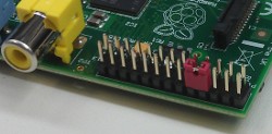
...Serial Loopback trick
The quickest way to test a Serial interface is to loop TX to RX using either a wire or a jumper ! When you write a data, you will receive it so you can read them back. When using the Serial monitor all data sent will be displayed back in the input area.
Serial Monitor

Python Serial basis
With REST mapping
Just like with the other devices set in the config file, you need to use webiopi.deviceInstance to retrieve configured Serial device :
def loop():
    serial = webiopi.deviceInstance("serial") # retrieve device named "serial" in the config
    serial.writeByte(0xFF)                    # write a single byte
    serial.writeBytes([0x01, 0x02, 0xFF])     # write a byte array
    serial.writeString("some text")           # write a string

    if (serial.available() > 0):
        value = serial.readByte()             # read and return a single byte
        print("0x%X" % value)

        values = serial.readBytes(3)          # read 3 bytes and return an array
        print(", ".join("0x%X" % i for i in values))

        data = serial.readString()            # read available data as string
        print(data)

    webiopi.sleep(1)
Be careful when using the REST API (with the Serial monitor) as well as using it from a custom script, you may notice strange behavior if you read data in your script. When data is received, it can be read only once.
If you need computation on the Pi, it's better to not set the Serial device in /etc/webiopi/config and create it by yourself in your script.
Without REST mapping
There is no much difference from the previous example, you just need to import Serial from the correct module, then you can instantiate a Serial object, passing the tty name and baudrate.
import webiopi
from webiopi.devices.serial import Serial

serial = Serial("ttyAMA0", 9600)

def loop():
    serial.writeByte(0xFF)                # write a single byte
    serial.writeBytes([0x01, 0x02, 0xFF]) # write a byte array
    serial.writeString("some text")       # write a string

    if (serial.available() > 0):
        value = serial.readByte()         # read and return a single byte
        print("0x%X" % value)

        values = serial.readBytes(3)      # read 3 bytes and return an array
        print(", ".join("0x%X" % i for i in values))

        data = serial.readString()        # read available data as string
        print(data)

    webiopi.sleep(1)
Arduino Streaming example
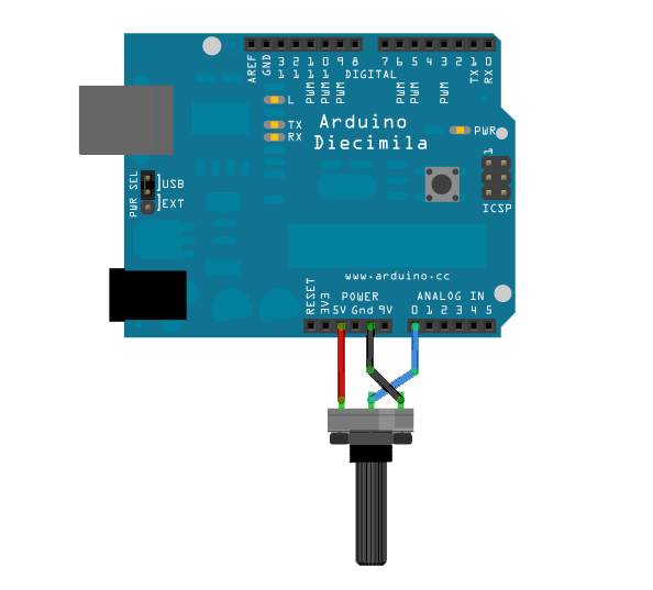
You will need an Arduino with something to monitor thought the analog input. It can be a thermistor, a photo-resistor, or anything you own. I'll take a simple potentiometer so I can change analog value by hand.
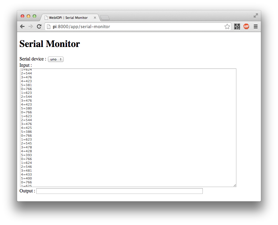
Arduino Sketch
Upload following sketch on your Arduino board using your computer. The sketches reads all analog inputs and write the values on the Serial interface each seconds.
int analogValue = 0;
int i;

void setup() {
  // open the serial port at 9600 bps:
  Serial.begin(9600);
}

void loop() {
  // read the analog input on all pins :
  for (i = 0; i<=5; i++) {
    analogValue = analogRead(i);

    // print it on serial
    Serial.print(i);
    Serial.print("=");
    Serial.println(analogValue);
  }

  // delay 1 second before the next reading:
  delay(1000);
}
Serial Monitor Test
You can then connect your Arduino to the Pi with the USB cord, set the appropriate Serial device in /etc/webiopi/config, then start WebIOPi to open the Serial Monitor.
Python : Processing data
Instead of using Javascript Serial library, I prefer consume Arduino data directly on the server side, within a custom script, and provide a macro to ease UI interfacing. Disable Serial REST mapping by commenting or removing Serial setup from /etc/webiopi/config
import webiopi
# import Serial driver
from webiopi.devices.serial import Serial
# initialize Serial driver
serial = Serial("ttyACM0", 9600)
sensors = [0 for a in range(6)]
def setup():
# empty input buffer before starting processing
while (serial.available() > 0):
serial.readString()
def loop():
if (serial.available() > 0):
data = serial.readString() # read available data
lines = data.split("\r\n") # split lines
count = len(lines) # count lines
lines = lines[0:count-1] # remove last item from split which is empty
# process each complete line
for pair in lines:
cv = pair.split("=") # split channel/value
channel = int(cv[0])
value = int(cv[1])
sensors[channel] = value # store value
webiopi.sleep(1)
# this macro scales sensor value and returns it as percent string
@webiopi.macro
def getSensor(channel):
percent = (sensors[int(channel)] / 1024.0) * 100.0
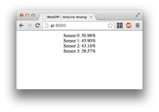
return "%.2f%%" % percentJavascript : Displaying values
If you followed macro and device tutorials, you should easily understand
following index.html. There is only few HTML
<div> and <span> which will be
filled in the macro callback, used by 4 macro calls.
<!DOCTYPE html PUBLIC "-//W3C//DTD HTML 4.01 Transitional//EN" "https://www.w3.org/TR/html4/loose.dtd">
<html>
<head>
    <meta http-equiv="Content-Type" content="text/html; charset=UTF-8">
    <title>WebIOPi | Arduino Analog</title>
    <script type="text/javascript" src="/webiopi.js"></script>
    <script type="text/javascript">
        webiopi().ready(init);

    // defines function passed previously to webiopi().ready()
    function init() {
        // automatically refresh UI each seconds
        setInterval(updateUI, 1000);
    }

    // function called through setInterval
    function updateUI() {
        // call getSensor macro for Arduino analog channel 0-3
        webiopi().callMacro("getSensor", 0, sensorCallback);
        webiopi().callMacro("getSensor", 1, sensorCallback);
        webiopi().callMacro("getSensor", 2, sensorCallback);
        webiopi().callMacro("getSensor", 3, sensorCallback);
    }

    // callback function used to display sensor data
    function sensorCallback(macroName, channel, data) {
                // use jQuery to change spans content
        $("#sensor"+channel).text(data);
    }

    </script>
</head>
<body>
    <div align="center">
    <div>Sensor 0: <span id="sensor0"></span></div>
    <div>Sensor 1: <span id="sensor1"></span></div>
    <div>Sensor 2: <span id="sensor2"></span></div>
    <div>Sensor 3: <span id="sensor3"></span></div>
    </div>
</body>
</html>
Save your files, and edit /etc/webiopi/config :
[SCRIPTS]section : add your Python script-
[HTTP]section : set doc-root to point to the folder containing your index.html -
[DEVICES]section : ensure you don't have a Serial device with the same tty
You can then start WebIOPi and open your browser.
Arduino Commands example
We will reuse the same wiring as before, with a potentiometer (or anything else) plugged in the Analog Input 0. We will also read Digital Input 2, so you may need either a button or a single wire to change input value.
Arduino Sketch
Upload following sketch on your Arduino board using your computer. It read Serial inputs for single char command (t/a/d), and responds by writing back time, analog, or digital input.
char input;

void setup() {
  // open the serial port at 9600 bps:
  Serial.begin(9600);
  pinMode(2, INPUT);
}

void loop() {
  if (Serial.available() > 0) {
    input = Serial.read();
    switch (input) {

      // "t" command: returns time in millis since reset/powerup
      case 't':
        Serial.println(millis());
        break;

      // "a" command: read and returns analog channel 0
      case 'a':
        Serial.println(analogRead(0));
        break;

      // "d" command: read and returns digital channel 2
      case 'd':
        Serial.println(digitalRead(2));
        break;

      default:
        break;
    }
  }
}
You can then connect it to your Pi with the USB cord and edit /etc/webiopi/config to add the Serial device.
[DEVICES]
uno = Serial device:ttyACM0 baudrate:9600
You an eventually try the 3-commands protocol using the Serial monitor.
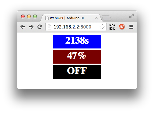
Javascript : Displaying values
Now create a new index.html, and add basic HTML structure, with
webiopi.js loading, a place for the Javascript code, and few CSS rules.
We will use 3 <div> to display results.
<!DOCTYPE html PUBLIC "-//W3C//DTD HTML 4.01 Transitional//EN" "https://www.w3.org/TR/html4/loose.dtd">
<html>
<head>
    <meta http-equiv="Content-Type" content="text/html; charset=UTF-8">
    <title>WebIOPi | Arduino UI</title>
    <script type="text/javascript" src="/webiopi.js"></script>
    <script type="text/javascript">
    // Javascript code will go here

    </script>

    <style type="text/css">
    #time, #analog, #digital {
                margin: 5px 5px 5px 5px;
                width: 160px;
                height: 45px;
                font-size: 24pt;
                font-weight: bold;
                color: white;
        text-align: center;
        background-color: Blue;
    }

    </style>
</head>
<body>
<div align="center">
    <div id="time"></div>
    <div id="analog"></div>
    <div id="digital"></div>
</div>
</body>
</html>
In the Javascript part, we will automatically and successively call all commands each seconds. Sequencing commands ensure to receive expected data.
    // declare variable for Serial object
    var serial;

    webiopi().ready(init);

    // defines function passed to webiopi().ready()
    function init() {
        // define Serial object, must be configured in /etc/webiopi/config
        serial = new Serial("uno");

        // automatically refresh UI each 5 seconds
        setInterval(updateUI, 1000);

        // update UI now
        updateUI();
    }

    // function called through setInterval
    function updateUI() {
        // retrieve Time
        getTime();
    }

    // function to use "t" command
    function getTime() {
        serial.write("t");
        serial.read(timeCallback);
    }

    // function that will process received data from getTime function
    function timeCallback(data) {
        // rounds milliseconds to seconds
        millis = parseInt(data);
        seconds = parseInt(millis/1000);

        // use jQuery to display seconds elapsed since Arduino reset
        $("#time").text(seconds+"s");
        getAnalog();
    }

    // function to use "a" command
    function getAnalog() {
        serial.write("a");
        serial.read(analogCallback);
    }

    // function that will process received data from getAnalog function
    function analogCallback(data) {
        // scales analog value to percent and to 0-255 range
        value = parseInt(data);
        percent = parseInt(value/1024 * 100);
        red = parseInt(value/1024 * 255);

        // use jQuery to display percent value
        $("#analog").text(percent+"%");

        // use jQuery to change color from black to red
        $("#analog").css("background-color", "rgb(" + red + ", 0, 0)");
        getDigital();
    }

    // function to use "d" command
    function getDigital() {
        serial.write("d");
        serial.read(digitalCallback);
    }

    // function that will process received data from getDigital function
    function digitalCallback(data) {
        value = parseInt(data);

        // set appropriate color and text depending on value
        if (value == 1) {
            $("#digital").css("background-color", "Red");
            $("#digital").text("ON");
        }
        else if (value == 0) {
            $("#digital").css("background-color", "Black");
            $("#digital").text("OFF");
        }
    }
Save, and change doc-root in /etc/webiopi/config accordingly to your working folder, then start WebIOPi to enjoy your Arduino UI.